Categories
MEP

Zero-Water Cooling and Closed-Loop Circularity in AI Data Centers: The MEP Engineering Imperative

The AI boom is responsible for environmental costs that extend far beyond electricity consumption. Across the United States, AI data centers are straining water supplies at a scale that most communities were never prepared to accommodate. According to market research, AI data centers consumed almost one trillion liters of water in 2025, equivalent to nearly 264 billion gallons.

The engineering profession, especially MEP engineering, now bears a direct responsibility for designing the next-gen data center infrastructure to evade this trajectory. Two technologies, zero-water cooling and closed-loop circularity, are reshaping what that infrastructure should look like.

The Water Toll of Traditional Data Center Cooling on US Communities

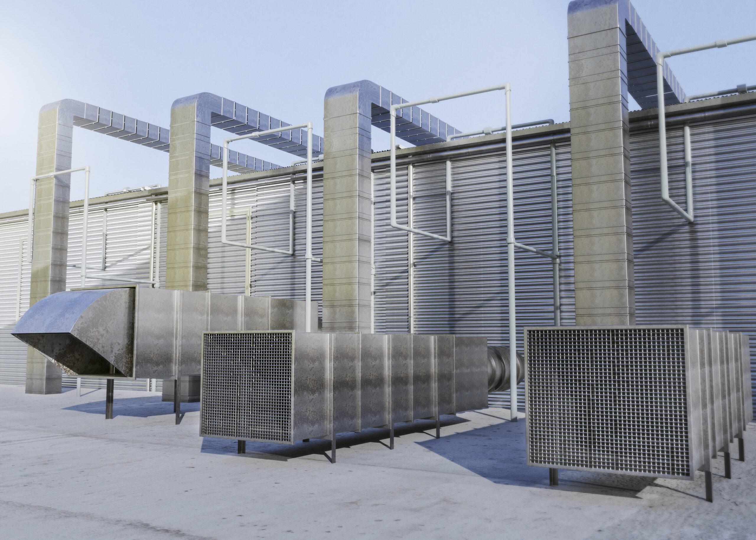
Conventional data center cooling depends on open-loop evaporative systems that use water at rates most people find hard to fathom. A mid-sized data center consumes around 300,000 gallons of water every day, a consumption rate on par with roughly 1,000 US households. In hyperscale AI facilities, this consumption can reach up to 5 million gallons per day.

The geographic reality exacerbates the urgency. A Bloomberg News analysis revealed that over 160 new AI data centers have already been built in water-stressed areas across the US over the last three years, a steep 70% increase from the prior period. Google’s Council Bluffs, Iowa, facility alone consumed 1.3 billion gallons of potable water in 2024. MSCI analyzed roughly 14,000 global data center assets and found that one in four may face elevated water scarcity by 2050.

Conventional evaporative cooling uses between 1 and 2.5 liters of water per kW of IT load. For high-density AI rack settings, where individual racks currently consume up to 140 kW, this consumption framework is not operationally or ecologically defensible.

Zero-Water Cooling Technologies Redefining What Data Centers Can and Must Be

The industry pivot toward zero-water cooling resonates with both environmental necessity and the physical limits of traditional approaches. Air cooling reaches a thermal management ceiling of approximately 70 kW per rack, well below the power density required by the latest AI hardware. Liquid transfers heat roughly 24 times more efficiently than air, making water-free liquid cooling the best course of action for high-density AI workloads.

The best-in-class zero-water technologies now entering extensive deployment include the following:

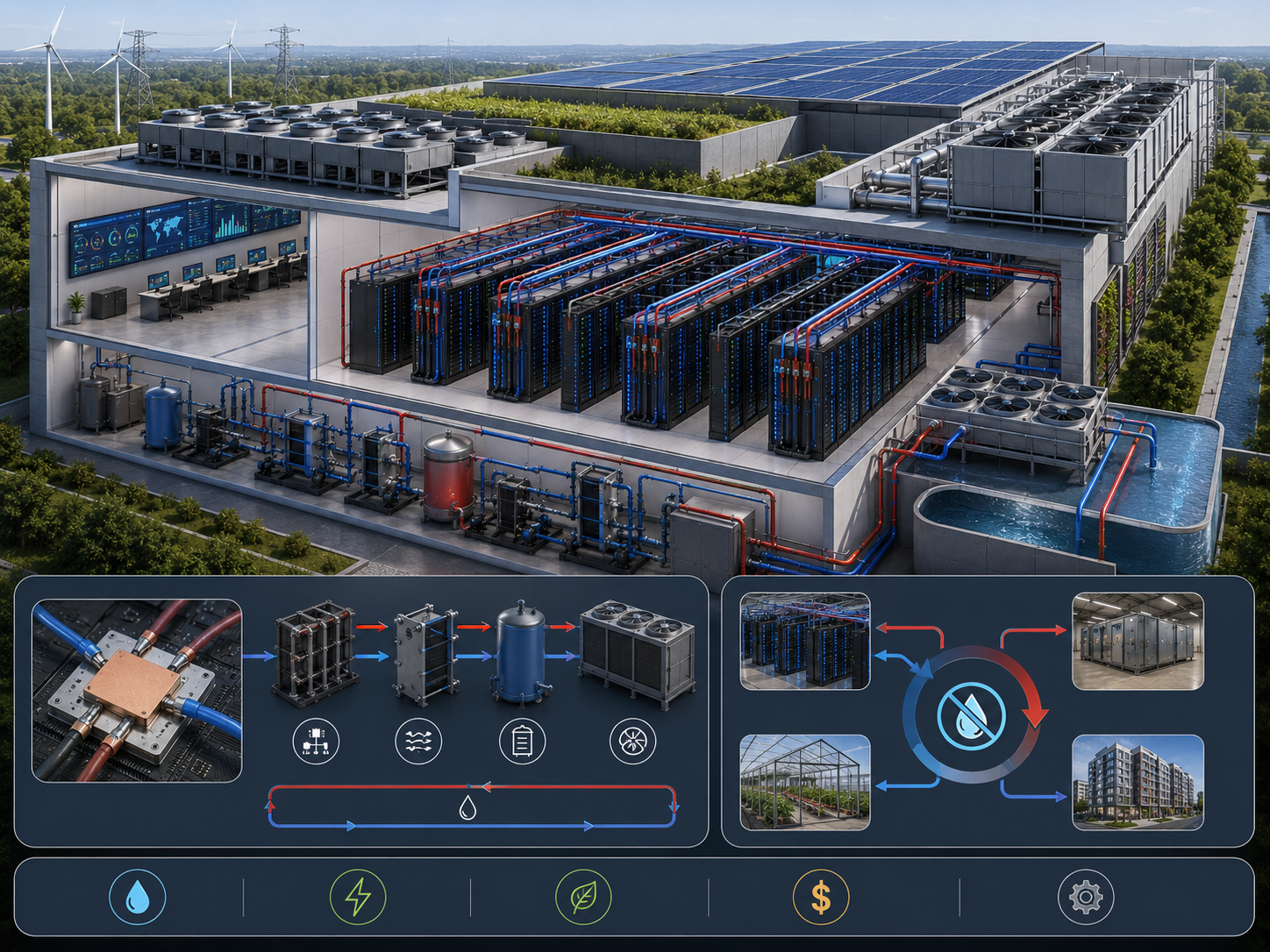
  • Direct-to-Chip (DTC) Liquid Cooling

It involves cold plates mounted straight onto processors that remove heat at the source, leveraging sealed coolant loops, thereby completely eliminating the need for room-level air conditioning or evaporative water towers.

  • Single-Phase and Two-Phase Immersion Cooling

In the single-phase method, engineers submerge servers in non-conductive engineered fluids that capture heat without water consumption. Two-phase systems, in which fluid boils and recondenses in a closed vessel, offer higher heat-flux capacity and a lower 10-year total cost of ownership.

  • Closed-Loop Chip-Level Cooling

Microsoft began incorporating sealed chip-level cooling systems into all of its new data center designs in August 2024, saving over 125 million liters of water per facility per year.

  • Rear-Door Heat Exchangers (RDHx)

This system uses heat exchangers mounted on the rear doors of server racks that absorb heat before it can enter the room, reducing or eliminating reliance on air-side cooling systems.

As of 2024, liquid-based cooling systems accounted for 46% of the overall data center cooling market, with the global data center cooling market valued at $10.8 billion in 2025 and forecasted to reach $25 billion by 2031.

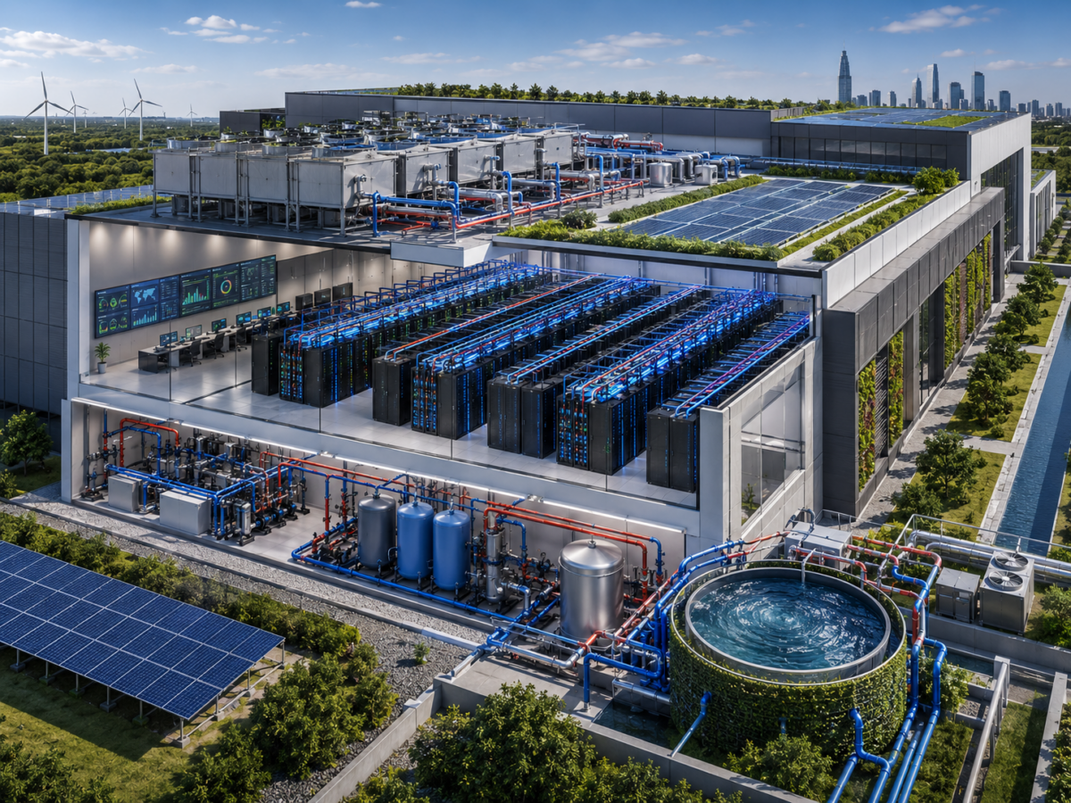
Designing Water Out of the Waste System: Closed-Loop Circularity

Zero-water cooling and closed-loop circularity are complementary tactics that cater to diverse design objectives. The former eliminates evaporative consumption, while the latter addresses the full lifecycle of thermal energy in a facility, essentially converting waste heat from cooling systems into a recoverable resource.

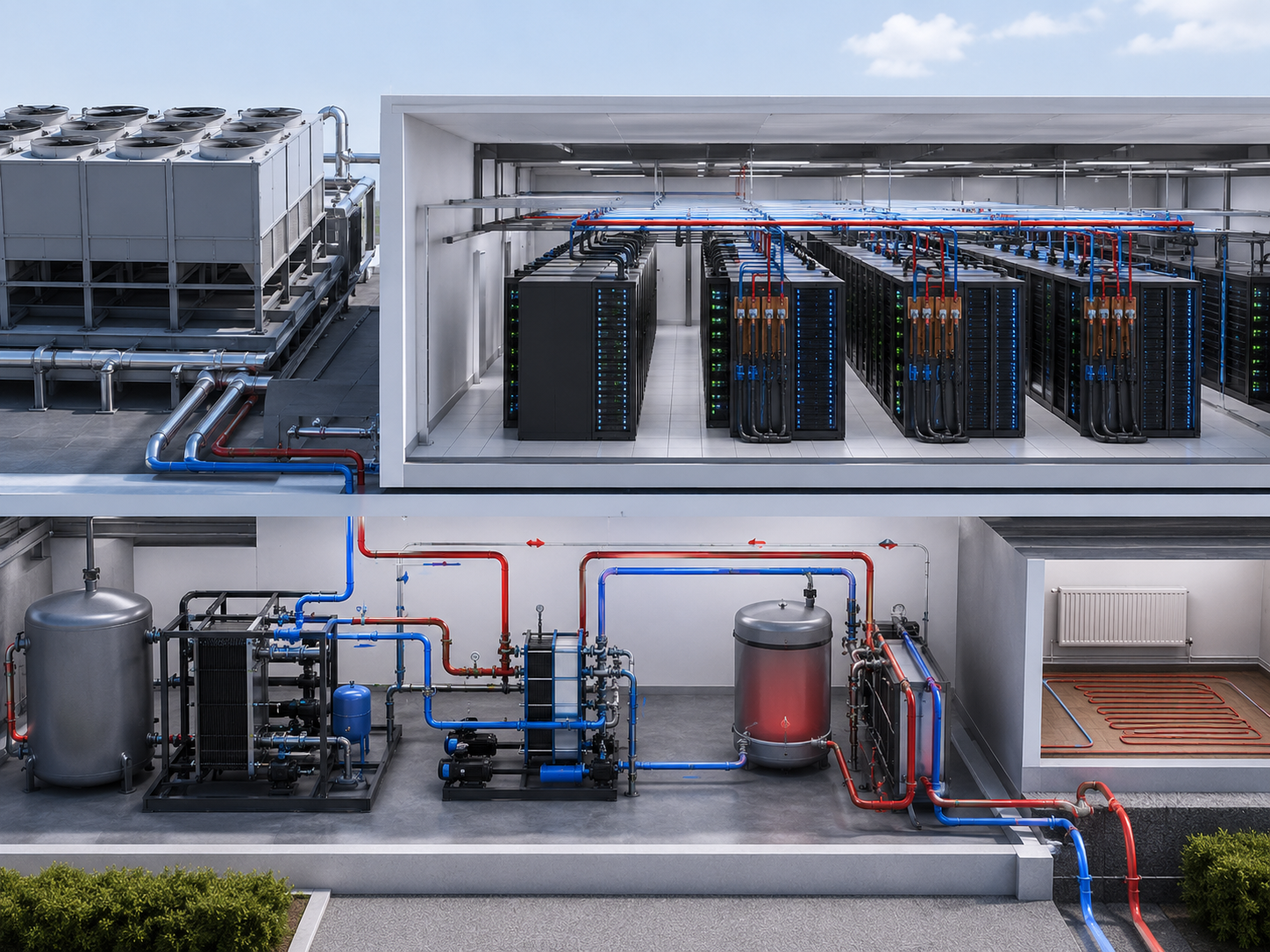
In closed-loop designs, coolant or working fluid circulates nonstop within sealed piping networks, capturing heat from servers and transferring it to dry coolers, heat recovery units, or district heating connections, with no water loss or atmospheric exposure. Microsoft’s closed-loop architecture, once filled at the time of construction, works indefinitely without needing extra water input. The technology giant reduced its Water Usage Effectiveness (WUE) from 0.49 liters per kWh in 2021 to 0.30 liters per kWh by 2024, with zero-water designs targeting WUE approaching zero.

Closed-loop systems also facilitate heat recovery integration with adjacent building systems, district networks, and on-site energy programs. They help transform what was previously a wasted thermal byproduct into a net-positive energy resource for neighboring infrastructure.

Next-Gen MEP Engineering for Zero-Water and Closed-Loop Systems’ Viability

Deploying zero-water cooling and closed-loop circularity in high-density AI data centers is inherently an MEP engineering challenge. Every single discipline within MEP ought to evolve to accommodate these systems, and the coordination among them should reach a higher standard than traditional commercial construction necessitates.

The critical MEP engineering responsibilities throughout this new design paradigm entail the following:

  • Mechanical and HVAC Engineering

MEP experts need to design and size closed-loop chilled water or coolant distribution systems, heat rejection infrastructure, dry cooler arrays, and precision temperature control strategies that sustain chip-level thermal tolerances in the absence of evaporative backup.

  • Plumbing and Fluid Systems Engineering

Chemical treatment protocols for closed-loop fluid integrity, redundant piping layouts with live leak detection, and supply and return headers sized for variable AI workload demands all require specialized plumbing engineering expertise from the preliminary design stage.

  • Electrical Systems Engineering

High-density power distribution supporting 80-150 kW per rack, alongside uninterruptible power systems and redundant electrical infrastructure, should be perfectly coordinated with cooling system power loads to meet facility-wide energy performance targets.

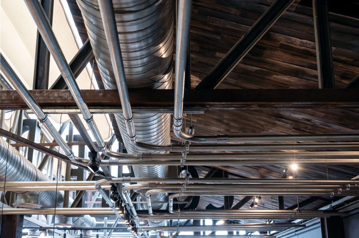
  • BIM Coordination and Clash Detection

In data center ceiling plenums where mechanical ductwork, electrical conduit, coolant piping, cable trays, and fire protection lines must coexist in a tightly constrained space, BIM-coordinated MEP design is imperative for constructability.

  • Sustainability and Energy Compliance

MEP professionals should incorporate WUE and PUE benchmarking, sustainability performance objectives, and energy code compliance into the design from the SD phase onward rather than treating them as post-design authentication tasks.

MEP Engineering Expertise to Match the Scale of the Challenge

The transition to zero-water cooling and closed-loop circularity in AI data centers is no longer a future-focused ambition. It is a workflow and regulatory expectation that takes shape across the US construction market right now. Architects, architectural firms, and general contractors engaged in data center projects need MEP partners who understand the end-to-end technical depth of what these systems require.

National MEP Engineers provides the MEP and sustainability design expertise that large-scale AI data center projects demand. Our licensed engineers deliver robust MEP system design throughout all project phases, from the SD phase through permit-ready construction documents, with sustainability-emphasized engineering built into each deliverable. For AEC teams designing next-gen US data center infrastructure, National MEP Engineers is the specialized partner that brings the in-depth technical expertise and delivery standards these projects need today.

Categories
MEP

What Makes an MEP Drawing Set ‘Permit-Ready’ And Why It Matters

When an MEP drawing set stalls at permit review, the cost is immediate: project delays, correction cycles, and missed occupancy deadlines. Yet many architectural firms and general contractors submit sets that are technically incomplete without realizing it.

A permit-ready MEP drawing set is not simply a polished schematic. It is a documentation package structured to satisfy regulatory scrutiny from the Authority Having Jurisdiction. In today’s construction environment, where AHJ requirements vary by region and code cycles update regularly, meeting that standard requires more than basic layouts.

AHJs now require drawings that show HVAC zoning, electrical service configurations, plumbing risers, equipment schedules, and code-referenced annotations. Accurate system coordination, complete technical specifications, and verified system integration are the baseline — not optional additions.

When permit reviewers detect inconsistent calculations or ambiguous layouts, they call for corrections. The consequence is that projects get delayed. This makes architects and general contractors rely on MEP drawing prowess to meet occupancy deadlines and avoid rework.

This article will outline the essential elements of a permit-ready MEP package and explain its importance in the current construction landscape.

What AHJs Actually Look for in an MEP Permit Submission

Approval-ready MEP drawing sets ought to demonstrate holistic compliance with regional building codes and national guidelines. AHJs use fundamental requirements to review submitted documentation. 

These requirements are grounded in three model codes: the International Building Code (IBC), which governs occupancy and structural requirements; the National Electrical Code (NFPA 70), which covers all electrical system design; and the International Mechanical Code (IMC), which governs HVAC, ventilation, and exhaust systems. Submitted MEP drawings serve as legal documents and must verify system safety, operational performance, and compliance with these standards at every stage of construction.

The Core Documentation Elements Every Permit-Ready Set Must Include

Permit-ready MEP drawings must include specific technical items that AHJs require for approval. These elements include:

  • Detailed equipment schedules with manufacturer specifications and performance ratings.
  • Complete load calculations confirming required system capacity and safety margins in accordance with ASHRAE 90.1 and the applicable IECC climate zone.
  • Thorough routing diagrams portray spatial coordination among all building systems.
  • Code compliance documentation referencing the adopted editions of the IBC, IMC, NFPA 70, and any state or municipal amendments.
  • Integration plans represent coordination with fire protection and life safety systems.

Together, these components give reviewing authorities everything they need to assess system adequacy and confirm code compliance during the permit evaluation.

The Regulatory Codes That Govern MEP Permit Approval in the U.S.

AHJ approval processes have evolved significantly, requiring compliance with multiple regulatory frameworks governing MEP design and installation.

The International Energy Conservation Code (IECC) directly governs HVAC equipment selection by setting minimum efficiency ratings, insulation values, and envelope performance thresholds that vary by climate zone. Where states have adopted their own energy codes, such as California Title 24, those take precedence over the base IECC, and MEP documentation must explicitly reference the adopted edition and any state amendments. 

The NFPA suite of codes governs the integration of fire protection systems across three primary standards: NFPA 13 for sprinkler system design and installation, NFPA 72 for fire alarm and signaling systems, and NFPA 101 (Life Safety Code) for occupancy-specific egress and life safety coordination. Each requires explicit cross-referencing in MEP documentation.

ASHRAE Standard 90.1 sets minimum energy-efficiency requirements for commercial building HVAC systems, lighting power density, and building-envelope performance. Most U.S. jurisdictions accept ASHRAE 90.1 compliance as an alternative path to IECC compliance for commercial projects.

What Permit-Ready Mechanical Drawings Must Demonstrate

Mechanical drawings must demonstrate complete system integration and verified performance to satisfy permit requirements. HVAC load calculations must confirm equipment sizing based on envelope performance, building occupancy, and operational requirements, and must comply with ASHRAE Standard 90.1 efficiency thresholds for the relevant IECC climate zone. When mechanical ventilation rates are involved, calculations must also meet the ASHRAE Standard 62.1 minimums for the applicable occupancy classification.

Ductwork layouts must show routing, sizing, and connection details for every zone, with sufficient clearances documented for maintenance access. Ventilation rates must meet the minimums established by ASHRAE Standard 62.1 for each occupancy classification present in the building, with outdoor air quantities and exhaust rates documented in accordance with the IMC. 

Electrical Drawing Requirements for NEC Compliance and Permit Approval

Electrical drawings for permit submission must demonstrate full compliance with NFPA 70 (National Electrical Code), covering power distribution, safety system integration, and emergency power provisions.

  • Power distribution diagrams must show service entrance configurations and panel schedules in sufficient detail for reviewers to verify load capacity and circuit protection.
  • Branch circuit layouts must include overcurrent-protection sizing and grounding-system details that comply with NEC requirements.
  • Photometric calculations must accompany lighting layouts to demonstrate that illumination levels and lighting power density meet the minimums set by ASHRAE 90.1 and the applicable occupancy requirements under NFPA 101.
  • Emergency power integration must document backup energy capacity and automatic transfer switching configurations in compliance with NFPA 110, and must show coordination between the normal and emergency distribution panels.
  • Fire alarm and telecommunications drawings must be coordinated with all other building systems to confirm spatial compatibility and signal integrity.

Together, these components confirm that electrical systems meet NFPA 70 requirements for the relevant occupancy type, with fire alarm systems additionally referencing NFPA 72 and emergency power systems referencing NFPA 110.

What the Documentation Must Cover for Plumbing and Fire Protection

Plumbing documentation must include water supply calculations that verify adequate pressure and flow rates for all fixtures, drainage system layouts with correct sizing and slope, and fixture schedules confirming compliance with the International Plumbing Code (IPC),  or the Uniform Plumbing Code (UPC) in Western U.S. jurisdictions, and applicable water conservation requirements.

Waste and vent systems should also be in good working order. They require accurate isometric drawings that show appropriate sizing and slope requirements. Another vital aspect of this provision is that fire protection systems demand perfect coordination with structural and architectural components. This is to ensure ideal coverage and accessibility for maintenance operations.

Sprinkler layouts must show head spacing, water supply capacity, and connection to the alarm system in accordance with NFPA 13. Hydraulic calculations must verify system performance for the relevant occupancy classification as defined by NFPA 13, and accessibility documentation must meet NFPA 25 maintenance requirements.

Quality Control Checks That Prevent Permit Rejections

Complete quality control means ensuring permit-ready drawing precision and regulatory adherence. It involves:

  • Interdisciplinary coordination review: Each MEP discipline is checked against the others to confirm that systems do not conflict spatially or operationally, and that all code requirements are met across the full set.
  • Calculation verification: Load calculations, equipment sizing, and performance specifications are independently checked to confirm they support the design intent and meet code minimums.
  • Drawing accuracy check: Dimensions, annotations, and specifications are reviewed for internal consistency across all sheets to catch discrepancies before they reach the reviewer.
  • Code compliance audit: Each drawing is checked against the adopted editions of the IBC, IMC, NFPA 70, IPC or UPC, NFPA 13, and ASHRAE 90.1, including any state or municipal amendments that modify the base code requirements for the project jurisdiction.
  • Constructability review: Installation sequences and site feasibility are assessed to confirm that the design as drawn can be built without conflicts or coordination issues in the field.

These procedures are of great value. They can shorten permit review cycles and aid efficient approval procedures that uphold project schedules.

How BIM and Cloud Platforms Support MEP Drawing Accuracy

BIM platforms have become central to producing accurate, permit-ready MEP documentation. 3D coordination within these platforms identifies system conflicts before they appear in submitted drawings, and integrates directly with calculation software and automated drawing generation tools to maintain consistency across all disciplines.

Cloud-based collaboration platforms enable live coordination among design teams, reviewers, and project stakeholders throughout the documentation process. Together, these tools support faster review cycles and more reliable approval outcomes. Version control systems ensure every stakeholder is working from the current drawing set, reducing the on-site conflicts and change orders that arise from outdated documentation.

Energy Modeling and Sustainability Requirements in MEP Permit Sets

Energy modeling is now a standard requirement in MEP permit submissions across most U.S. jurisdictions. Calculations must validate HVAC system efficiency and building envelope performance against the thresholds set by the adopted IECC edition, or demonstrate equivalent compliance through ASHRAE Standard 90.1. Where renewable energy systems are included, their integration must also be documented in accordance with the applicable state energy code.

Sustainable design documentation must address water-conservation measures, indoor-environmental-quality provisions, and energy-efficient system selections. For projects pursuing green building certification, these elements must align with the relevant LEED credit requirements or the applicable jurisdiction’s green building code, many of which reference ASHRAE Standard 189.1 for high-performance building criteria.

Conclusion

Permit-ready MEP documentation is the foundation for project timelines, budget certainty, and regulatory approval. In a landscape where AHJ requirements grow more detailed with each code cycle, the quality of the drawing set determines whether a project moves forward or stalls.

National MEP Engineers produces MEP drawing sets built to meet AHJ requirements across U.S. jurisdictions. Our documentation process covers load calculations, equipment schedules, coordination drawings, and code compliance references, everything a permit reviewer needs to approve the submission without a correction cycle.

If your next project requires permit-ready MEP drawings that hold up under AHJ scrutiny, get in touch with National MEP Engineers to discuss your requirements.

Categories
MEP

The Hidden Triggers Behind MEP Redlines & How Early Planning Prevents Them

Every architect and general contractor is aware of the sinking feeling of receiving a redlined package. Red marks throughout MEP drawings mean rework, delays, and budget exposure that no one planned for. What most teams miss, though, is that MEP redlines can sometimes result from careless mistakes. They originate from specific, repeatable triggers that infiltrate during the earliest design phases.

Research confirms that rework expenses generally account for between 5% and 8% of overall project costs. For a moment, consider only MEP systems: they alone consume 30% to 40% of total commercial construction expenditures. This combination makes every unaddressed MEP conflict a costly problem.

Therefore, understanding in detail what really causes MEP redlines and fixing those causes before they multiply is among the highest-leverage decisions that architects and GCs can make in any project.

The Main Cause Most Teams Never See Coming

The hard truth is that most MEP redlines do not result from field errors. In the real world, they emerge in design-phase decisions that seem nonthreatening at the time.

Architectural layouts are often settled before MEP experts provide meaningful input. This sequencing is precisely where trouble begins. When architects finalize ceiling heights and shaft dimensions before sizing HVAC ductwork, conflicts become unavoidable. If electrical room locations are decided in the absence of load summary input, panel clearance breaches follow.

The project experience coordination issue is compounded by the fact that MEP systems are deeply interdependent. For instance, due to their size and rigidity, ductwork cannot be rerouted in a day when a structural beam is blocking it. Moreover, a plumbing stack placed incorrectly can affect fire protection riser locations above it.

GCs and architects need to comprehend that every unidentified conflict in design accumulates into multiple redlines later. Industry surveys show that 10-15% of total project expenses can go toward rework, with MEP systems hit hardest. Fortunately, these are predictable triggers, and when identified early, they can change the whole course of the outcome.

The Most Consistent Hidden Triggers Behind MEP Redlines

Keep in mind that not all MEP redlines are created equal. Some come from ethical process gaps that keep surfacing project after project. Understanding these recurring triggers helps GCs and architects actively safeguard schedules and budgets. These are the covert triggers that initiate MEP redlines most consistently in all US construction projects:

  • Late MEP involvement locks shaft dimensions and ceiling heights before HVAC and plumbing systems are sized
  • Missing interdisciplinary coordination between MEP routing and structural shop drawings generates on-site conflicts at beams and slabs
  • Undocumented scope alterations mid-design push MEP systems into configurations that do not align with structural or architectural elements anymore
  • Insufficient space allocation in ceiling plenums and mechanical rooms requires on-site rerouting and expensive access cuts
  • Changing code requirements during multi-year projects lead to compliance bottlenecks when MEP designs are not updated accordingly
  • Incomplete electrical load summaries make panel schedules disconnected from real equipment demands, resulting in correction cycles

Every single one of these triggers is avoidable. Recognizing these triggers before design development is complete enables architects and GCs to eliminate the redline cycles that result. Proactive detection at the SD phase costs only a fraction of what field correction demands.

Why Timing Is Everything in Avoiding Redlines

Among the most crucial things that GCs and architects can internalize is the dramatic increase in the cost of fixing an MEP conflict as a project progresses.

An HVAC routing conflict spotted in SD takes a significant amount of time to resolve. If the same conflict is discovered during CD, it can be dealt with in just a couple of days. When the conflict is detected at the site, it can completely halt the entire trade sequence. So, proactive MEP coordination, commencing at the SD phase, consistently yields better outcomes.

On the other hand, MEP experts’ engagement during the SD phase greatly influences ceiling height choices, shaft sizing, and equipment room locations before finalizing them. This early-stage input effectively eliminates the source conditions that produce redlines.

Contractors leveraging coordinated BIM models prior to construction report about 40% fewer RFIs during installation. Clashes detected and fixed at the design phase have signified an ROI of 10 to 1 on documented projects.

Establishing weekly MEP coordination touchpoints during DD allows architects to experience quantifiably cleaner permit submissions. From the perspective of general contractors, fewer RFIs indicate minimal schedule disruptions and lower administrative overhead per project.

How Early Planning Methodically Removes MEP Redlines

There was a time when people considered early planning a vague concept. Over time, it has become evident that it is, in fact, a methodical set of decisions and workflows that GCs and architects can incorporate into every project. The goal here is to make conflicts easily visible while solutions remain within an affordable range.

The following are the particular early planning initiatives that most efficiently stop MEPO redlines from forming:

  • Involve MEP specialists at SD so they can influence shaft locations, ceiling heights, and equipment room sizing from the beginning
  • Conduct interdisciplinary BIM coordination using Revit and Navisworks clash detection prior to issuing CD sets
  • Set up a BIM execution plan at the start of the project that outlines routing hierarchies, exchange formats, and clash resolution procedures
  • Validate ceiling plenum depths against the actual HVAC duct sizing, sprinkler mains, conduit bundles, and insulation build-ups concurrently
  • Execute organized coordination meetings at the conclusion of every design stage to confirm all traders’ optimal working conditions from the same model

All these steps move critical decisions to the stage where they cost the least to modify. GCs and architects who prioritize embedding these steps into their standard project operations consistently deliver clearer CD packages with minimal permit corrections.

Clearly, front-loading coordination investment is the best direct approach to protect both project margins and client relationships.

Final Notes

The preceding discussion evidences that MEP redlines do not have to be inevitable. They are basically the predictable outcome of coordination shortcomings that form early and emerge late. Architects and GCs with a detailed understanding of the hidden triggers behind MEP redlines can stop them before they compound across a project.

Early MEP involvement, methodical clash detection, and disciplined coordination at the SD and DD phases should be initiated first. They help remove the conditions that produce redlines. Always remember that every dollar spent on preemptive coordination can save thousands of dollars in downstream rework expenses.

To avail exactly this kind of proactive, early-stage MEP coordination service, National MEP Engineers is among the most prominent choices. Once partnered with architects and general contractors, we ensure your project stays out of MEP redlines by effectively fixing hidden triggers at the very start.

Our MEP and fire protection services are formulated around PE-led, coordinated documentation that precisely mitigates the hidden triggers behind MEP redlines before they become major obstacles in the field. Connect with National MEP Engineers today and make MEP redlines a struggle your upcoming projects will never face.

Categories
Uncategorized

Top Construction Documentation Production Firms in North Carolina

Even the strongest design concepts can stall if the construction documentation isn’t clear. Recognizing this, AEC firms in North Carolina are always on the lookout for the right CD production support provider.

It is key to understand that today’s projects move rapidly, and teams seldom have to deal with busy AHJs, tight deadlines, and high client expectations. Therefore, unclear or incomplete documentation can completely derail a project.

This is why many modern AEC firms are leaning on dedicated partners capable of delivering unwavering quality in construction documentation. Collaborating with such a partner from early design phases can ensure your project’s buildability throughout. Moreover, it also helps the project with easier review and keeps it aligned with budgets from the outset of design stages through final construction documents.

Many think it is all about reducing workload, but in reality, a trusted documentation partner plays an even more vital role in tackling project risk. Jurisdiction code knowledge, familiarity with approval procedures, and robust digital workflows all make a quantifiable difference after drawings move to construction.

This blog outlines six high-quality construction documentation production providers that support all types of building projects across North Carolina.

Uppteam is one of the most prominent names in the United States offering exceptional AEC support services. With over 250 experts across engineering design disciplines, the company has successfully delivered over 4,800 projects since its inception. When it comes to client satisfaction, Uppteam has consistently delivered exactly what clients asked for, never deviating from a single project’s real objectives.

Concerning construction documentation production, the company has a unique service solution called “Architectural Offshore Production.” Essentially, this service uses a phase-based construction documentation production approach.

In North Carolina, Uppteam has worked on several projects over the years, indicating that this state’s AEC firms have considerable trust in the company’s quality deliverables. For architects and contractors in North Carolina, Uppteam’s AOP service helps increase documentation capacity. This means those firms do not have to worry about adding headcount for capacity expansion.

There are key phases in this AOP model: schematic design, design development, construction documentation, and final submission. All these phases mirror AIA workflows, allowing North Carolina-based firms to plug AOP into their existing procedures. For optimal quality assurance, the company leverages multilayer quality checks at every phase checkpoint.

LynxPros works directly with architecture practices across North Carolina through a specialized state-focused outsourcing program. The firm exemplifies support for conceptual design, schematic design, design development, and construction documentation. All these are delivered as an extension of a client’s in-house workforce.

LynxPros emphasizes permit-ready, code-adherent drawings for all regions within North Carolina, along with rendering and visualization support. This blend appeals to local AEC firms searching for a comprehensive design-to-documentation arc.

For AEC companies, LynxPros comes with a simpler way to offload drafting and BIM modeling while keeping client-facing decisions in-house. The vendor describes review loops where clients mark up drafts, and Lynx converts those comments into updated construction documents. This approach ensures the maintenance of design control.

So, if your firm is searching for flexible, project-focused CD production support, LynxPros should be considered when peak workload hits.

TeamCSI is a great option for interior-focused construction documentation in North Carolina. The business anchors its identity in interior design practices with over 30 years of experience producing construction documents for commercial infrastructures across the state. Its documentation offering includes plans, elevations, reflected ceiling plans, materials, and lighting layouts, all aligned with jurisdictional codes and client standards.

Moreover, TeamCSI connects documentation with project management, budgeting, and coordination services. This allows AEC clients to manage interiors from planning through completion under one umbrella. This integrated support from TeamCSI helps architects and GCs simplify coordination and curtail drawing-related RFIs.

As a result, AEC businesses operating in North Carolina that need robust construction documentation seldom consider TeamCSI a practical and reliable partner.

Turn Complex MEP Challenges into Simple Solutions
Our experienced team handles everything from system design to coordination—ensuring clarity, accuracy, and efficiency at every stage.

CAD Outsourcing is a clear ideal choice for AEC firms operating in North Carolina for a strict error-free construction documentation standpoint. One main reason is that the company provides this support worldwide, not just in the US. So, global expertise is a big plus for architects and general contractors seeking the right CD production partner in the state.

Besides, the company also offers top-tier BIM modeling and CAD drafting services. Its BIM practice generates 3D models with in-depth architectural, structural, and MEP content, then utilizes those models to develop coordinated drawings and quantity takeoffs.

For North Carolina firms already working on BIM-heavy projects, a global support partner like CAD Outsourcing can supplement modeling and documentation activities in line with clear standards.

The provider underscores the use of major industry-standard platforms like Navisworks, Revit, and BIM 360, as well as experience working with architects, contractors, and engineers. This technology stack and cross-disciplinary comfort make CAD Outsourcing a standout option when North Carolina teams need dependable external assistance with complex documentation production.

KCA Design Studios is the last firm featured in this list of CD producers in North Carolina. The organization facilitates AEC firms in this state with comprehensive architectural solutions, with particular emphasis on construction document creation. KCA markets complete CD development for design-build deliveries and conventional project structures.

The firm exemplifies a focus on timely and economical documentation that supports both visually refined and functional spaces. In fact, this balance lines up perfectly with the requirements of owners and contractors who seek clarity without overdesign.

KCA ties its CD production to feasibility studies, design development, and collaborative project work.

This end-to-end approach ensures clients move from site selection to ready-for-permit drawings with a single core design partner. For that reason, KCA is frequently chosen by AEC firms looking for both local architectural leadership and solid CD production support.

Final Thoughts

North Carolina’s construction market is expanding rapidly. What is important to understand is that documentation accuracy has a significant impact on every project’s success. It is imperative that architects and GCs in this state carefully assess each potential partner’s code familiarity, software stack, and geographic reach. Opting for a capable CD production partner is among the smartest choices any North Carolina AEC business can make today.

Some of these firms support their projects by working closely with National MEP Engineers for MEP-related requirements. We deliver coordinated MEP, fire protection, and energy modeling assistance to nationwide AEC organizations. Our US-licensed PE-led MEP designs are built to seamlessly integrate with your firm’s construction documentation workflow in the Tar Heel State.

Categories
Uncategorized

Top Construction Documentation Production Firms in Georgia, USA

Even if your design ideas are great, you need flawless construction documentation to succeed. Architects and contractors in Georgia are well aware of this fact. It is understandable that strict schedules, challenging AHJ reviews, and busy on-site crews leave little room for ambiguity in drawings today. That is why AEC firms are increasingly relying on niche construction documentation production partners that emphasize coordinated BIM and code-aligned CD packages.

These teams help keep projects within the forecasted budget while protecting the design intent from schematic design to the final submission of construction documents.

When an AEC firm takes on a project in Georgia, its choice of documentation partner fundamentally shapes both risk and profitability. The commercial construction industry in Georgia alone generates over 80 billion USD in economic output annually. Such a figure reflects the project pipeline of the AEC firms in this state. Undoubtedly, with so many active projects, AEC firms need construction documentation production partners they can rely on.

The right collaborators have a detailed understanding of Georgia codes, digital coordination, and the realities of jobsite sequencing. This article lists some of the best construction documentation providers that can actively support projects across Georgia.

Uppteam When it comes to top-quality CD production support, many Georgia-based architects and contractors have unwavering trust in Uppteam. The architectural offshore production services of Uppteam work as an extension of AEC firms’ in-house teams.

The AOP service model is focused on taking schematic concepts and design development ideas from AEC firms and converting them into fully coordinated, ready-for-permit construction document sets. US-licensed architects at Uppteam set standards and monitor quality, while the production team deals with detailing, coordination, and sheet production at scale.

For Georgia projects, AEC firms can gain particular value from Uppteam’s methodical SD, DD, and CD phase deliverables, which adhere to AIA-style milestones and US drafting conventions. The company concentrates on BIM models, multi-layer QC, and code-conforming detailing so RFIs and change orders are kept to a minimum on complex builds.

If your firm is looking for a reliable documentation partner, Uppteam should definitely be on your list of considerations as a focused production engine that supports regional staff with demanding workloads.

Tejjy Inc., an 8(a) certified women-owned business offering high-quality BIM and construction documentation services in Georgia. With almost 17 years of experience in this field and having completed more than 2,500 projects throughout the country, Tejjy has positioned itself among the leading AEC-related service providers.

Georgia-based AEC firms should know about the following capabilities of Tejjy’s construction documentation:

  • BIM experts develop BIM Execution Plans with organized workflows for every Georgia project.
  • Architectural BIM services comprise 3D visualization, thorough construction drawings, and façade shop drawings.
  • Multidisciplinary clash detection for architectural, structural, and MEP systems to eliminate high-cost field conflicts.
  • Construction documentation involves 2D drawings for architectural, MEP, fire protection, and structural design.

GCs and architects in Georgia have been trusting Tejjy for its coordinated, code-compliant construction documentation for all project types.

USA Draftsman, is often considered in Georgia by AEC professionals for their construction documentation requirements. As a matter of fact, if you are looking for a documentation production partner originating directly from Georgia, USA Draftsman must be on your shortlist.

The company offers thorough 2D blueprints, 3D BIM drafting, and construction documentation in line with the state’s building codes and approval pathways. Architects and general contractors always rely on this type of regional familiarity when they deal with municipal submittals. USA Draftsman’s team also highlights fast turnaround on site plans, trade schematics, and floor plans. All these elements help GCs to keep preconstruction moving seamlessly.

For leaders overseeing both schedule and budget, local support is always helpful in reducing coordination friction and travel requirements for field clarifications. USA Draftsman endorses itself as a trustworthy partner for commercial, residential, and infrastructure projects seeking compliant documentation production without additional overhead.

Looking to Streamline Your MEP Design Process?
From concept to construction documentation, National MEP Engineers delivers coordinated MEP solutions that reduce rework and speed up approvals. Trusted by AEC professionals across the USA.

MARS BIM, is another leading name in construction documentation production in Georgia. The company serves the Georgia market with its BIM drafting and construction documentation solutions. MARS BIM positions itself as a partner that supports architects, structural engineers, and MEP teams with coordinated 3D models and in-depth drawing packages.

Specifically in Georgia, this organization’s offerings include BIM drafting, production of construction documents, construction simulation, family creation, and 4D scheduling assistance. All these services convert directly into more error-free drawings and fewer clashes when projects reach the construction phase.

Numerous MARS BIM project examples demonstrate its strong modeling and construction documentation capabilities, helping projects control RFIs and stay within the baseline budget. If you are an AEC leader looking for a partner with proficiency in BIM-driven workflows and installation-focused documentation, MARS BIM can be a great choice.

VARMINE BIM, Another well-recognized construction documentation production support provider in Georgia. With a focus on serving AEC businesses across this state, VARMINE specializes in architectural construction documentation and BIM coordination. Their team serves the needs of architects, engineers, and general contractors across Georgia.

On one hand, the company produces Revit architectural models from drawings, sketches, and point cloud scans. On the other hand, Varmine’s construction documentation deliverables include as-built drawings, architectural 3D modeling, shop drawings, and Revit family creation.

By taking advantage of LiDAR, Digital Twins, drone inputs, and GIS data, VARMINE ensures highly accurate documentation. Moreover, GSA-conformant BIM services also help federal construction projects in Georgia needing dedicated documentation assistance.

Exceptional expertise in documentation and detailed regional knowledge make this company a great choice for AEC firms seeking error-free CD production.

Bimpact Designs rounds out this list of top construction documentation production firms in Georgia. This firm describes a team experienced and highly skilled in architectural, structural, and MEP BIM, as well as Revit drafting support for all project types.

Many AEC firms in this state have placed their trust in Bimpact due to its phase-wise production of construction document sets. The company also leverages a three-step, quality-centric VDC workflow that covers SD through final CD sets.

A specialized team at Bimpact provides assistance in architectural Revit modeling, 2D CAD drafting, and Revit family creation.

The architectural Revit models created by Bimpact maintain LOD progression standards from conceptual design through permit-ready CD development. BIM Execution Plans guide the documentation workflow and keep all disciplines aligned throughout a project.

So, overall, Bimpact offers integrated support that can lead to more predictable CD sets. The company’s experience in global markets also provides local architects and contractors with an additional option when they need to rapidly scale production capacity without compromising CD quality.

​Conclusion

Clearly, AEC firms working in Georgia do not lack documentation options today. Actually, the challenge is in matching each project’s risk profile and schedule pressure with the ideal fusion of CD production partners. Some AEC organizations favor close collaboration with local providers who are extensively familiar with regional jurisdictions. Others lean toward national support providers of CD production who bring exceptional capacity and multidisciplinary coordination expertise.

The most important thing for architects and GCs is whether the chosen partner can consistently safeguard design quality while helping budgets remain within initial projections.

Categories
MEP

What Architects Should Expect from a High-Performing MEP Partner

Architects and general contractors are aware that a wrong MEP partner can subtly disrupt even the strongest design. Minor coordination gaps in HVAC, power, or plumbing result in RFIs and change orders.

However, with a high-performing MEP partner, architectural teams move from concept to permit with minimal surprises and far less stress. Honestly, this difference matters even more now, as clients lobby for expedited schedules and stricter energy and safety performance.

From the very beginning, architectural firms need a clear picture of what good MEP engineering design looks like. In this blog, we will lay out practical expectations for a high-performing MEP partner, rooted in existing best practices, BIM coordination research, and recent project metrics.

The focus here is simple: help decision-makers of US-based AEC businesses identify the workflows, traits, and technical depth that realistically safeguard their projects.

The Importance of Having the Right MEP Partner for Architects

The efficiency of modern buildings depends more on MEP systems than on their structure or finishes. MEP partners capable of delivering high performance treat these systems as the foundation of safety, overall performance, and long-term operational expenses. They step into the schematic design phase with specific load assumptions, energy goals, and code pathways. There is no room to wait for late design handoffs. Because of this early engagement, layouts remain realistic, and mechanical rooms or shafts are not considered an afterthought.

In fact, recent coordination studies reveal how much this matters. Rework stemming from design conflicts can be significantly curtailed if BIM-based clash detection is leveraged. In fact, a large share of general contractors across the US now report that proactively prioritizing early BIM coordination resolves clashes well before construction work starts. They have also experienced a considerable reduction in RFI and change order volumes.

So, architects or architectural firms should expect their MEP partners to lean into this reality and not perceive coordination as merely a box-ticking practice at the end.

Main Technical Capabilities Architects Must Insist On

There is much more than just drafting capacity that high-performing MEP partners bring to the table. Modern architects need to see direct, licensed engineering leadership on each project, supported by an organized quality control procedure.

US-based PEs specify system criteria, review calculations, and sign off on permit packages. Then, production teams convert that direction into coordinated construction documentation within a common BIM environment.

Considering the mechanical side, architects should expect in-depth HVAC load calculations, meticulous equipment positioning, and cautious routing that respects ceiling heights and architectural intent.

On the electrical side, the right MEP partner should be able to offer clear power distribution, emergency systems, lighting layouts, and panel schedules. They must also ensure that these elements are always in alignment with the NEC and regional codes.

On the plumbing and fire-protection front, partners are required to deliver code-conforming water, gas, and sprinkler systems in integration with architectural and structural limitations.

One final capability that architects expect from their ideal MEP partner is the energy modeling and Title 24 or IECC documentation to support design choices. Architects don’t want their MEP partner to consider these documentary norms to be an afterthought when permit deadlines are near.

Collaboration Behaviors That Safeguard Design Intent

Technical proficiency won’t matter much if the MEP partners can’t work the way architects do. This implies that design teams need to seek partners who organize their operations around SD, DD, and CD milestones, with unambiguous expectations at every stage.

Strong partners engage early during the concept conversations. They translate program requirements into system strategies and flag any limitations before drawings are finalized. They take advantage of BIM not just as a modeling tool but as the primary coordination workspace across disciplines.

Let’s not forget that communication is equally important. Another critical expectation of modern architects is a single, accountable point of contact who can address design questions ASAP and keep discussions moving. High-performing teams respond to RFIs with specific, coordinated answers that reference the most updated models. They also record decisions so that on-site teams always know which version is current.

Evidently, these habits keep confusion to a minimum and help preserve design intent under strict schedules.

BIM and Coordination Practices Architects Must Seek

Right now, architectural firms are at a critical juncture, recognizing that there is no alternative to BIM coordination. Nevertheless, architects should still closely examine how an MEP partner really runs that process.

The best firms treat BIM as the focal point for multidisciplinary decision-making rather than a deliverable manufactured in isolation.

Architectural firms must opt for MEP partners who:

  • Coordinate every discipline together within a single Revit or similar BIM model rather than in separate silos.
  • Run clash-detection cycles and track resolutions regularly.
  • Utilize coordinated models to preserve space for piping, ducts, and risers so trades don’t fight for ceiling space later.
  • Join BIM workflows to fabrication or prefabrication where feasible. This supports GCs in compressing timelines without compromising quality.
  • Share models and viewpoints with architects so everyone can see coordination choices in context.

In this regard, it is worth mentioning that project-level studies now confirm that disciplined BIM coordination can notably lower RFIs and change orders. Your MEP partner must build those coordination practices into its standard delivery model.

Signs of an Actual High-Performing MEP Partner

As a matter of fact, architectural firms look for signals that ensure a potential MEP partner is capable of performing optimally under pressure. Some of these signals emerge in proposals and kick-off conversations. The rest of them appear at the early stages of design. It is crucial to understand that both matter when projects are moving quickly.

The most important sign involves:

  • Clear expectations regarding how the partner will assist with SD, DD, CD, and construction support.
  • Proof of multi-state code familiarity, such as IBC, IMC, IPC, IFC, NEC, ASHRAE, NFPA, and Title 24 where relevant.
  • Proven use of BIM-based coordination and documented quality control procedures that lessen redesign.
  • Metrics that highlight fewer RFIs, minimal change orders, and expedited permitting on comparable work.
  • A pragmatic approach to sustainability that favors reliable, maintainable solutions over feature-driven yet fragile technologies.

It is also vital that architects listen to how MEP teams discuss collaboration. High-performing MEP support providers speak in the realm of shared accountability, timeline protection, and design intent. This attitude makes a huge difference by predicting how they will behave when inescapable pressure comes.

Final Notes

Let’s set something straight first. Architectural forms don’t just need MEP drawings. They actually want an MEP partner who can help them deliver efficient, safe, and buildable projects with no continuous firefighting.

High-performing MEP teams feature licensed engineering leadership, best-in-class BIM coordination, and workflows aligned with architectural milestones.

National MEP Engineers positions itself as a remote, expert-level provider of MEP design services. Our MEP solutions are built around precisely the expectations discussed above for architects and architectural firms throughout the US.

If your architectural firm is looking for a high-performing MEP partner, there is none better than the National MEP Engineers. Contact us now!

Categories
Uncategorized

Top Construction Documentation Production Firms in Florida, USA

Did you know that in 2024 alone, Florida issued more than 173,000 building permits? Yes, it is the reality and reflects the state’s humongous construction demand. In fact, construction contributes significantly to this state’s GDP.

With over 5,000 architectural firms present in Florida, competition for quality projects is relentless. AEC firms operating in this region need trustworthy construction documentation production partners to win projects and finish them efficiently and with confidence.

Opting for the ideal construction documentation production partner changes outcomes on each project. We know that ready-for-permit, coordinated CD packages curtail AHJ review comments, on-site RFIs, and expensive change orders.

Architectural firms and  general contractors deserve partners who can deliver documentation precision at every phase. This article walks you through the top construction documentation production firms supporting the AEC business across Florida today.

Uppteam is a dedicated provider of architectural production services, including construction documentation support for US-based AEC firms. Florida AEC businesses use Uppteam to extend their construction documentation capacity without increasing internal team size.

US-licensed architects with over 25 years of experience in this field lead each engagement, starting with schematic design through final submission. Uppteam leverages Autodesk Revit and Autodesk Construction Cloud for live BIM collaboration across all project stages.

The following are the deliverables of Uppteam’s architectural offshore production services in Florida:

  • Production teams adopt the Revit templates, drawing standards, and sheet numbering of the client from the very beginning
  • A US-based regional representative handles all communication, accountability, and delivery expectations closely with the specific client
  • Phase-wise deliverables at 30%, 60%, 90%, and 100% keep each CD checkpoint schedule on track
  • AI-facilitated quality control at 90% CD phase spots documentation errors prior to the final submission

There are several examples of Florida-based AEC firms gaining scalable construction capacity with no expensive in-house overhead.

ENG is the next big name in this list. This firm is among the largest providers of BIM and construction documentation in the US. Established in 2007, ENG has delivered more than 7,000 successful projects nationwide.

ENG has become a prominent name among the Florida-based AEC firms for its architectural Revit production and complete CD deliverables. Moreover, this organization’s Florida portfolio entails major projects in Tampa, Fort Pierce, Orlando, Miami, and Jacksonville.

With a workforce of 700+, ENG consistently delivers scalable production capacity qualified for any type of project. The architectural production team at ENG provides support for SD, DD, and comprehensive CD-phase documentation.

The firm follows every client’s Revit templates and standards as if working internally at the client’s office. ENG guarantees code-compliant reviews for IBC, ADA, ICC, and NFPA standards, protecting every project in Florida. The reputation of this firm is such that architects and GCs in Florida trust ENG for code-adherent, constructible construction documentation on every project.

United-BIM Inc. is a certified SBE/MBE business offering BIM and construction documentation services throughout the Sunshine State. The firm understands this state’s construction codes, climate challenges, and local permitting specifications across all jurisdictions.

No matter the scale or type of a project, AEC firms rely heavily on United-BIM’s efficiency. United-BIM also produces structural, architectural, and MEP models across different LODs. Their clients report cost savings of around 40% in hiring, training, and overhead expenses.

Coordinated Revit documentation from this organization supports Florida contractors in avoiding expensive RFI cycles. Construction documentation services from this firm stay in sync with AHJ permitting requirements across all jurisdictions in the state.

Here are Advenser’s deliverables for construction documentation clients:

  • Developing construction documentation sets from coordinated BIM models in line with client standards
  • Scan-to-BIM solutions for renovation projects translate point clouds into precise Revit models
  • Clash detection and VDC coordination address discipline conflicts ahead of the start of construction work
  • Documentation sets align with the plan, detail view, sheet set, and permit submission specifications

All in all, United-BIM is a certified, reliable, and experienced partner for error-free construction documentation creation and delivery in Florida.

Need MEP Engineering Services for your next project?
National MEP Engineers provides full-scale mechanical, electrical, plumbing design services, fire protection and energy calculations for AEC firms across the USA. High accuracy. Fast turnaround. Competitive pricing.

Designing Drafting has slowly become a trusted partner for AEC businesses due to its exceptional BIM modeling and construction documentation services tailored for Florida projects. Architects and contractors in this state have immense trust in this organization for its outstanding capabilities in Revit 2D and 3D CAD documentation.

Design Drafting is also specialized in architectural Revit modeling, CD production, and site plan layouts. The firm develops BIM models from schematic design to final construction documents. Coordinated BIM models integrate every discipline’s documentation for all types of projects.

BIM automation specialists at Designing Drafting follow international BIM codes and norms on all project submissions. Every single construction document produced by the firm aligns perfectly with Florida building codes and industry standards. This methodical approach assists with seamless AHJ reviews. With Designing Drafting as a partner, AEC firms benefit from rapid turnaround times for commercial, residential, and institutional CD packages.

Advenser offers construction documentation services to all architectural firms and general contractors in the US. AEC businesses leverage Advenser for full CD packages encompassing architectural, structural, and MEP disciplines. The firm utilizes BIM to create comprehensive, error-free construction documents across all engineering trades.

Applying ISO 19650 BIM standards, Advenser ensures optimal information management quality in every project phase. The company's construction documentation services include code compliance validation and multidisciplinary clash coordination.

Many of Advenser’s architectural and contractor clients have reported that the firm uses a structured QA approach that effectively reduces AHJ review comments consistently. The firm generates coordinated Revit-based drawings for all disciplines. Ready-for-permit documentation created by Advenser expedites approval cycles and safeguards project schedules for Florida-based AEC firms. The organization also supports these firms from the early DD phase through complete permit-ready CD package delivery.

Tesla Outsourcing Services, next big name in this list. Tesla is known for delivering standardized, code-conformant construction documentation to US AEC firms. Over 300 leading AEC companies trust this firm’s CD set delivery. The main reason for this reliability is the production of AutoCAD- and Revit-based CD packages that comply with every local building code to the highest precision.

The company uses a workflow that covers SD, DD, and working drawings for commercial and residential projects. Tesla conducts a thorough screening of thousands of architects to select the best experts for every project. BIM-enabled CD packages allow architects to reflect 3D model changes constantly across all project phases.

Through its flexible engagement, Tesla enables AEC businesses to scale construction documentation support as project workloads evolve. The experts at Tesla ensure that architects and GCs receive clear, coordinated drawings that minimize field conflicts considerably.

With over two decades of documentation experience, Tesla is positioned as a reliable name for Florida AEC businesses.

Wrapping Up

AEC firms in the Sunshine State of the US now have access to highly proficient CD production partners. The right CD production support provider delivers speed, precise coordination, and permit-ready CD packages every time.

Many of these top CD production companies in Florida have partnered with National MEP Engineers for their remote MEP design services. Get in touch with us today and elevate your upcoming Florida construction project with top-level MEP support.

Categories
MEP

How Architects and MEP Engineers Can Protect Design Intent Through Construction

Design intent is something that has to be strong on paper and through to the construction completion. However, it often starts strong but fades after construction has started on a busy site. In a way, design intent can seem fragile.

Substituting materials, making on-site adjustments, and hurried coordination can rapidly erode meticulously crafted concepts if teams don’t have the needed structure and support. Architects put enormous effort into coordinated design documents. Still, contractor RFIs and value engineering silently damage that vision. Understanding the reasons behind this is the first proactive step toward preventing it.

Where Design Intent Is Most at Risk During Construction

You would make a big mistake if you think design intent is limited to visual appearance. In fact, it also describes the aesthetic and functional goals reflected in drawings, specifications, and models.

Evidently, when there is a mismatch between design and construction, gaps naturally emerge quickly. We know that architects finalize documents and then deliver them to the contractors. This handoff is when any design drift occurs. Contractors substitute materials, reroute MEP systems, and relocate equipment without sharing this information with the design team.

MEP systems directly orchestrate many of these conflicts. The positioning of HVAC equipment affects ceiling heights and spatial quality. Electrical conduit routing disrupts the interior finish plan. Even plumbing chases compete directly with architectural partition layouts. It is critical to acknowledge that these trade-level decisions call for active coordination and not passive document review.

Architects and general contractors in the US must recognize a consistent pattern. We see RFIs compound in the absence of early integration of MEP systems. What follows are the change orders. Such disruptions extend a project’s budget and schedule. That is why early MEP coordination is the most effective first step to defend design intent.

MEP Coordination as the First Line of Defense

If you want to reliably protect your architectural vision, there is no better alternative than coordinating MEP systems early. Real-life examples repeatedly confirm that when MEP engineers start collaborating at the schematic design phase, spatial conflicts get fixed before becoming major issues in the field. Accordingly, ceiling heights stay intact, and equipment rooms remain fitted in planned zones.

On the other hand, BIM-based coordination is crucial because it provides architects and contractors with a common visual model. Clash detection with Navisworks or Revit spots system conflicts before construction work starts. This preemptive approach removes costly on-site modifications that mostly compromise project budgets and design quality.

Therefore, GCs and architects should implement the following main MEP coordination practices into every project workflow:

  • MEP specialists have to engage with the design team at the SD phase. This confirms system placements ahead of finalizing and locking in architectural layouts.
  • Clash detection reports should have every construction document submission, including all resolved and open MEP conflicts across disciplines.
  • Clear rules should be established for substitutions, reviews, and sanctions so that field modifications respect appearance, performance, and code obligations.
  • Weekly coordination meetings must have MEP, structural, and architectural teams addressing open EFIs collaboratively before on-site installation work.

When it comes to complex projects, most firms now depend on specialized MEP design partners. The main advantage is that while the partner runs clash detection, updates models, and responds quickly to RFIs, your architects and GCs remain focused on stakeholder alignment and site progress.

Documentation Precision to Safeguard Design Decisions

Remember that construction documents are the legal and technical record of design intent. Inadequately coordinated drawing packages leave contractors confused and lead to unauthorized field substitutions. This means architects need MEP drawings that align perfectly with architectural and structural layouts at all project phases.

Ready-for-permit MEP drawings necessitate comprehensive coordination prior to AHJ submission. Duct routing plans, equipment schedules, panel schedules, and riser diagrams should always resonate with the final architectural configuration. When documentation is incomplete, it results in permit comments that significantly delay project timelines.

Documentation of the mechanical rooms mandates top-level precision. Fully coordinated drawings should accommodate HVAC clearance zones, structural support specifications, and equipment access routes. Frequently, architects lose ceiling height when mechanical layouts remain unsettled through design development. GCs are prone to costly change orders when contractors encounter undocumented field conflicts.

Energy Compliance & Fire Protection as Design Anchors

Energy compliance and fire protection systems are crucial factors that carry particular design implications for architects. IECC specifications regulate HVAC system choice, lighting power density, and building envelope performance. These code norms directly impact spatial planning, ceiling design, and equipment positioning decisions during the entire course of a project.

As a matter of fact, fire protection systems are subject to equally significant coordination demands. Sprinkler head placement is a vital aspect that affects ceiling aesthetics. Besides, riser locations compete with the positioning of architectural shafts. Be mindful that both systems need code-motivated design decisions validated long before starting CD production.

It is the responsibility of the architects and GCs to answer these compliance-focused design questions before CD production initiates:

  • The chosen HVAC system must be consistent with IECC energy performance requirements to confirm the equipment efficiency rating during the DD phase.
  • Fire sprinkler head locations ought to coordinate directly with reflected ceiling plans. This protects all architectural finishes and interior design intent.
  • Lighting power density calculations need to uphold applicable energy code thresholds without sacrificing the architectural lighting scheme in all occupied spaces.

Sustaining Design Intent Using Active Construction Phase Support

Bear in mind that protecting design intent does not end when permit approval is gained. During the construction phase, MEP support ensures that the architectural vision remains consistent as contractors mobilize and install systems. Dedicated MEP support teams actively monitor site conditions and fix RFIs with design-friendly solutions.

Undoubtedly, submittal reviews are a critical milestone in the construction phase. Contractors often propose equipment alternatives during submittals that can feasibly downgrade system performance and spatial quality. So, MEP experts should assess every alternative against the original design criteria. When incompatible substitutions are approved, the outcome is long-standing performance issues that outlast project warranties.

Dedicated MEP support should also be able to swiftly respond to RFIs with documented, coordinated solutions. An unaddressed RFI contributes to contractor ambiguity, which then leads to field decisions that almost never match design intent. Therefore, prompt RFI responses are the shield for your construction schedule while ensuring architectural precision throughout the system installation period.

Conclusion

We can now confidently say that design intent survives construction when documentation, coordination, and compliance all work jointly. Architects and GCs who prioritize early MEP alignment can easily protect their project’s design intent throughout every phase. The needed discipline begins at schematic design and flows through final commissioning and occupancy.

National MEP Engineers is the MEP partner that architects and GCs across the US need. We deliver top-quality, cutting-edge MEP engineering support that no one else does. Our entire MEP services package integrates seamlessly into your workflow.

Connect with us and start protecting your design intent with sheer precision today.

Categories
MEP

Prevent ‘Cascading Changes’ in Commercial Projects Through Better MEP Planning

Have you ever seen one design choice unravel an entire commercial infrastructure project? In reality, that actually happens more than general contractors and architects realize. More often, the root cause of these failures is gaps in MEP coordination. Even a single unfixed MEP conflict can trigger cascading changes in multiple project operations. More interestingly, once that chain reaction begins, firms pay the price in terms of time and budget overruns.

Well, the good news here is that most cascading changes are completely preventable. GCs and architects who engage with MEP experts early evidently face minimal revisions. In this blog, we will walk you through how optimized MEP planning safeguards commercial projects from scope drift. It will also show the vital coordination gaps to resolve before they sink into bigger problems.

Impact of Cascading Changes in Derailing Commercial Projects

GCs and architects are well aware of how rapidly one design change can multiply. There are several real-life examples. Like an HVAC duct repositioning in last-minute construction documents can shift supply routing. This change collides with structural steel overhead. After that, ceiling heights need to be adjusted, and the lighting layouts need to be broken. Accordingly, electrical circuits require complete rerouting to match. It is truly surprising how one late decision can easily become five or six change orders.

This sequence repeats across all scales of US commercial projects far too often. Research shows that miscommunication accounts for 26% of all construction rework, and inaccurate project information drives another 14-22% of total rework expenses. Architects and contractors have to carry those expenses directly in every project stage. Weak MEP coordination makes it even more difficult to avoid these figures in commercial developments.

On the other hand, RFI holdups alone can defer a project’s completion schedule by up to 10%. Remember that each unsettled MEP clash on site comes with its own cascading timeline risk. In large-scale commercial projects, the routine generation of hundreds of MEP-related RFIs is common. As a matter of fact, early MEP coordination can break this chain prior to escalating costs and time.

Most Overlooked MEP Coordination Gaps by Architects & GCs

It is not that common for MEP conflicts to stay local. There comes a point when contractors and architects learn this eventually. A plumbing issue on one floor leads to a cascade two floors up. The majority of last-minute scope changes in commercial projects stem from coordination gaps between design and MEP engineering.

Unmistakably, involving MEP specialists early in the workflow addresses these gaps before they become major struggles. These coordination errors seldom result in cascading design changes in commercial projects:

  • Ceiling plenum limitations are missed early by HVAC design, and after that, duct reroutes damage the entire structural coordination.
  • Electrical panels contradict architectural components, and expensive layout changes follow in subsequent design phases.
  • Design teams position plumbing chases in the absence of cross-disciplinary input. Then, it becomes necessary to shift shaft locations in later phases.
  • Design development ignores fire protection riser locations, which then forces ceiling and lighting revisions during construction documentation.
  • Teams undersize mechanical equipment rooms during the schematic design stage. What we see next is trade sequencing conflicting when construction is underway.

General contractors should realize that they benefit most when MEP engineering input begins before the design hardens. It effectively curtails on-site conflicts, which are known to generate the most costly construction RFIs.

Why Mechanical & Electrical Engineering Should Come First

For architects working on commercial projects, HVAC systems demonstrate the most frequent cascade trigger. They know that ductwork routing depends directly on structural clearances, ceiling heights, and equipment room dimensions. In this scenario, mechanical experts need to assess these spatial constraints from the outset of the project. With no early input in place, architects lock in ceiling layouts without precise MEP space reservations.

Load calculations must also be completed at the schematic design stage. Equipment choice and appropriate sizing flow explicitly from those early numbers. Last-stage mechanical input indicates that spatial alignment occurs only after construction documentation is complete. Any HVAC reroute at that point negatively impacts the entire coordinated drawing package. Then, revisions compound throughout multiple disciplines at the same time.

Electrical engineering next introduces identical cascading risks when it enters the project too late. Here, keep in mind that panel sizing depends on aggregate loads from every building system. When electrical rooms are undersized, they enforce last-minute floor plan changes that cost architects several weeks. It is also worth noting that NEC-compliant conduit routing calls for structural clearance planning during design development. When you skip this, it contributes to on-site conflicts and high-cost RFIs during electrical rough-in.

Plumbing & Fire Protection Systems That Amplify Scope Changes

Throughout the US, architects and general contractors often undervalue the cascading potential of plumbing and fire protection systems. Plumbing design should include chase locations, drainage grades, and water risers from the earliest stages. Bear in mind that fire protection coordination ought to take place before ceiling and lighting layouts are finalized.

The following coordination failures are mostly responsible for triggering downstream scope changes in commercial projects:

  • Sanitary drainage grades need specific slab thickness, and late coordination makes structural redesign and floor plan revisions compulsory.
  • Hot-water recirculation loops require individual chase spaces, and shaft clashes occur once architects have finalized layouts.
  • Gas piping layouts must be coordinated very early in the process with equipment locations and structural penetration points.
  • Fire sprinkler zoning and riser locations need to be coordinated with ceiling, lighting, and HVAC systems from the start of design development.
  • Last-minute fire protection input makes ceiling revisions mandatory, impacting multiple disciplines and trades concurrently.

General contractors should be mindful of the actual cost of these gaps during rough-in and closeout. When early plumbing and fire protection coordination are prioritized, we see the prevention of most of these expensive late-stage scope changes.

Unified MEP Planning as a Project Risk Strategy

As an architect or GC, if you are committed to integrated MEP planning from day one, you can rest assured of stronger outcomes. This underscores the importance of involving MEP and fire protection experts from schematic design onward. Early coordination essentially establishes system-wide strategies and design protocols across disciplines. Architectural decisions remain unsettled before MEP input can properly shape them.

BIM-based coordination in Revit fosters cross-disciplinary clash detection before the first brick is laid on site. Research confirms that coordinated MEP BIM workflows significantly reduce errors and rework. For contractors, this means fewer RFIs and minimal change orders throughout the project. It also indicates greater schedule certainty at each major project checkpoint.

Architects benefit considerably when MEP input comes at the SD instead of the DD phase. When this input is prioritized during the SD phase, it helps prevent ceiling-height clashes, incorrect shaft sizing, and permit surprises. On top of that, it also guarantees the elimination of expensive design drift that often frustrates GCs and architects across all project phases.

Conclusion

Cascading changes don’t have to define project delivery of commercial developments. Architectural firms and general contractors dedicated to avoiding scope drift share a common practice. It is nothing other than early MEP coordination. Involving MEP experts from the start of the SD process ensures that every discipline is ideally aligned. It safeguards schedules, budgets, and permitting timeframes on every commercial project.

Under such circumstances, National MEP Engineers is the best partner you can have in the US. We deliver unified MEP support to GCs and architectural firms. Our licensed PEs cover MEP and fire protection from SD to permit-ready CDs. We leverage a three-layer QC process to minimize permitting friction and revision cycles on all projects.

So, for your next commercial project, partner with National MEP Engineers and experience guaranteed prevention of cascading changes through top-drawer MEP planning.

Categories
MEP

The MEP Decisions That Shape Building Layouts Long Before CDs Are Developed

There is a pattern that most general contractors and architects are familiar with. A layout gets locked in, then the MEP expert arrives, and everything changes. Consequently, equipment rooms end up in the wrong zones, ceiling heights shrink, and structural beams block duct runs. It is not that these clashes originate during the construction documentation. Instead, they surface from MEP decisions that were not made early enough. The real challenge is to get ahead of this cycle.

MEP systems influence spatial choices throughout the schematic design phase. Mechanical rooms, plumbing shafts, electrical risers, and fire protection zones all require spatial commitments before construction documentation begins. Every architect and GC in the US needs to recognize this dynamic, as it protects their budgets, schedules, and design quality from the very start.

Location of the Mechanical Room Drives Every Floor Plan Decision

During the conceptual design phase, MEP experts utilize simplified spatial models to allocate free space. This assures sufficient room for mechanical equipment, ceiling voids, and risers. Architects need these allocations verified before floor plans can advance past the schematic design.

According to research, HVAC and associated mechanical systems can take up to 30% of an infrastructure’s enclosed volume. Design teams customarily designate a minimum 3-foot ceiling plenum to accommodate MEP requirements. When this plenum is cut while performing value engineering, duct runs conflict with ceiling finishes and structural beams. An actual eight-story building of specific height can gain an additional floor when MEP coordination halves the plenum requirement.

SMACNA norms govern duct sizing, routing, and pressure classifications for every HVAC distribution system. Upholding these norms calls for structural clearances validated at the schematic design phase. When architects defer mechanical room placement, structural conflicts become unavoidable, which then generate expensive change orders in the design development phase.

Electrical Infrastructure That Finalizes Spatial Choices at the SD Phase

At the SD stage, electrical infrastructure seldom impacts the layout more than architects realize. One must be mindful of the main switchgear rooms and distribution panel locations requiring NEC-mandated clearances. These sanctions specify the room dimensions that resist revision after architectural layouts are finalized. No one wants to relocate a switchgear room once structural drawings have been issued.

It is the responsibility of the GCs and architects to address the following electrical spatial commitments at the earliest in the SD phase:

  • Main service entrance and switchgear room positioning should be in alignment with the requirements of the utility provider. This alignment must be ensured before locking in floor plan layouts at the SD phase.
  • Electrical riser shaft locations must be coordinated with structural bay spacing to avoid penetration conflicts.
  • Exhaust routing and the placement of the emergency generator need roof or grade-level space decisions, directly impacting both façade design and field planning.

So, clearly, the placement of the electrical room must be confirmed early. This ensures perfect alignment between architectural and structural decisions. It further evades any layout changes, which often disrupt permit schedules and amplify contractor bid pricing.

Plumbing Shafts That Directly Affect Structural Framing

Plumbing routing is another early-stage spatial commitment that architects must deal with at schematic design. Keep in mind that vent stacks, sanitary waste lines, and domestic water risers require exclusive shaft space, which must be validated prior to finalizing framing decisions. These shafts pierce structural members and call for coordination before structural specialists settle bay layouts and beam depths.

Wet wall positioning establishes partition layouts throughout the entire floor plates. When a plumbing core is positioned without structural input, firms experience cascading partition conflicts. General contractors encounter these misalignments as on-site change orders when plumbing shafts are installed in undocumented locations during construction.

When it comes to vertical distribution in multistory buildings, careful plumbing coordination is the key. Understanding that tight floor-to-floor spacing severely restricts MEP routing is also vital. This means plumbing risers ought to align with fixture layouts and fulfill venting and pressure requirements defined during the SD phase.

The Need for Fire Protection Zoning and Ceiling Coordination

The designs of fire protection systems matter a lot. They have a significant influence on both occupancy planning and ceiling coordination. Moreover, sprinkler head placement relies on occupancy classification, confirmed ceiling heights, and hazard group. Don’t forget that the AHJ review should commence at permit submission. Architects require confirmed occupancy classifications ahead of finalizing sprinkler density calculations. If you get this sequencing wrong, be ready for complete redesigns at the permit stage.

The following fire protection-related decisions need to be made by GCs and architects before SD concludes:

  • Confirming occupancy classification should precede sprinkler density calculations to stay clear of permit-stage redesigns.
  • Riser room and fire pump locations need to be integrated with architectural core planning to eliminate last-minute shaft relocations.
  • Ceiling height commitments for all occupancy zones should be in line with sprinkler head spacing requirements before reflected ceiling plans reach the design development stage.

Successfully dealing with the fire protection zoning at the SD phase safeguards permit timelines and removes cascading conflicts between architects, fire engineers, and structural teams during design development.

Energy Compliance & Its Impact on Early MEP System Selection

Complying with energy codes belongs in the SD-phase discussion, not during the CD review cycle. We know that IECC protocols govern HVAC system decisions, envelope performance, and lighting power density jointly. These specifications directly motivate how mechanical and electrical systems are sized, routed, and positioned across a building. Architects who give preference to addressing energy compliance early make smarter spatial decisions throughout every design phase.

On the other hand, building envelope choices made at the SD phase have a considerable impact on HVAC load calculations. Window-to-wall ratios, glazing specifications, and insulation methods change how mechanical systems are sized and where equipment finally lands.

When HVAC duct layouts are integrated within BIM models, they help curtail coordination clashes with other trades by approximately 20%. Such a notable reduction occurs only when energy-driven system choices are made sufficiently early to inform architectural layout decisions.

Final Thoughts

It is undeniable that MEP decisions taken during schematic design influence every single building layout that follows. So, those GCs and architects who prioritize addressing MEP requirements early can confidently protect their project timelines and design integrity throughout the entire project lifecycle.

National MEP Engineers brings top-quality MEP, fire protection, and energy compliance expertise into your SD process. Our proficient team integrates MEP spatial planning into your architectural workflow from the earliest design stage, led by licensed PEs.

Get in touch with National MEP Engineers now and start making foundational MEP decisions that secure your project layout from the very first day.